If you’ve already got your Datacase or just want to know how to set one up, you’ve come to the right place.

Notes
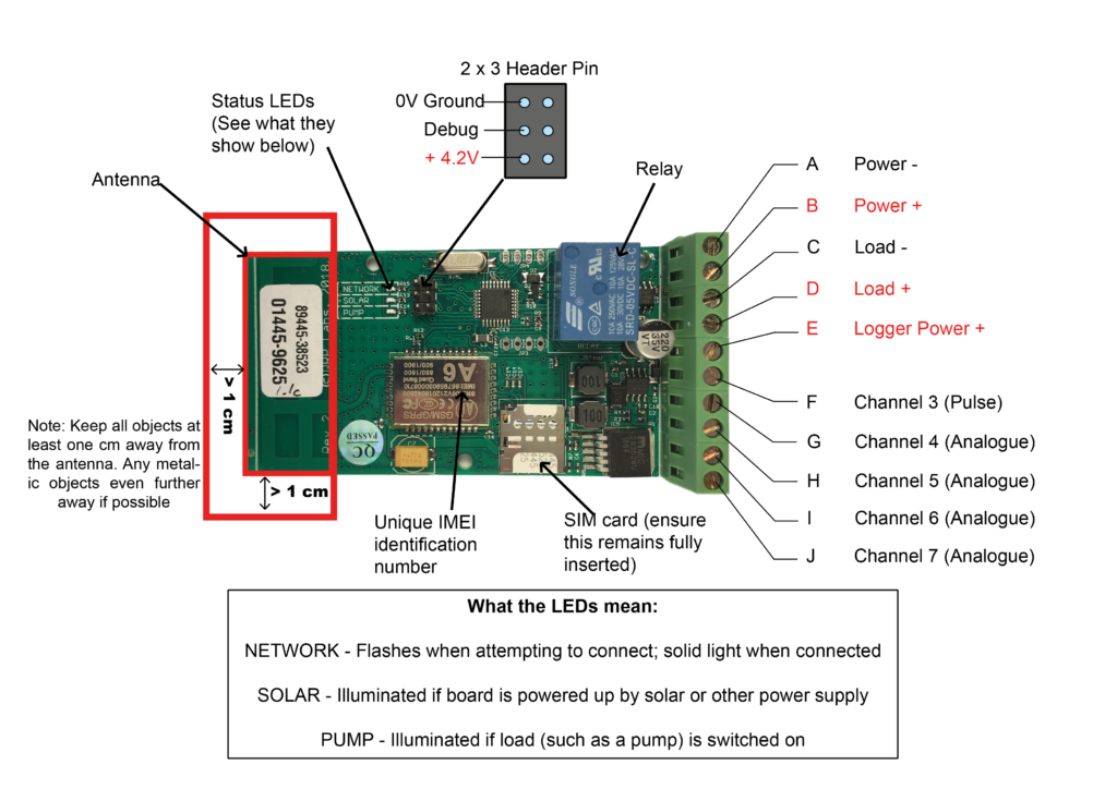
- A +4.2V supply, and a ground to power any additional sensors can be taken from the 2 x 3 pin header, as shown. But don’t exceed 30mA current draw from these pins.
- The Debug pin on the 2 x 3 header will deliver a serial output which can be helpful for debugging in case of connectivity problems. A debug serial cable is available separately.
| Terminal # | Labeled | Description | Notes |
| A | Panel – | DC voltage input (negative) | Input range 0 to 46.2V |
| B | Panel + | DC voltage input (positive) | Input range 0 to 46.2V |
| C | Pump – | Pump (or other load) output (negative). Optional | Onboard voltage is measured at Terminal D. Onboard current measurement is the current flowing from Terminal B to D and must be in the range 0 to 5A |
| D | Pump + | Pump (or other load) output (positive). Optional | Onboard voltage is measured at Terminal D. Onboard current measurement is the current flowing from Terminal B to D and must be in the range 0 to 5A |
| E | Logger supply + | Logger positive supply voltage | Range 7 – 35V, do not exceed this. If the logger supply voltage is less than 9.5V no attempt will be made to connect to the mobile network. For testing, a suitable setup is to put a jumper wire from Terminal B to Terminal E and have them both powered by say, 12V. |
| F | Channel 3 | Pulse count channel | Range 0 to 18000 counts per minute. Do not exceed 4.2V. |
| G | Channel 4 | Analogue sensor voltage +, 0 to 4.2V | Do not exceed 4.2V. Connect negative side of the sensor to the 0V header or Terminal A or C |
| H | Channel 5 | Analogue sensor voltage +, 0 to 4.2V | Do not exceed 4.2V. Connect negative side of the sensor to the 0V header or Terminal A or C |
| I | Channel 6 | Analogue sensor voltage +, 0 to 4.2V | Do not exceed 4.2V. Connect negative side of the sensor to the 0V header or Terminal A or C |
| J | Channel 7 | Analogue sensor voltage +, 0 to 4.2V | Do not exceed 4.2V. Connect negative side of the sensor to the 0V header or Terminal A or C |
Getting your data at getdatacase.com
Each channel is sampled 50 times per second, and the measurements are averaged and recorded each minute. Every fifteen minutes, fifteen sets of records are sent to your account at app.getdatacase.com via the mobile phone networks. Obviously, if there is no mobile reception at your location, it won’t work.
Your logger(s) will have been pre-assigned to your getdatacase account. Visit app.getdatacase.com and log in with your log in details.
Inside the app
Click on ‘Datacases’ in the left menu and you will see each Datacase you have bought has a six digit ‘Identifier’. Look for the last six digits of the IMEI number inscribed in tiny writing on the logger’s A6 modem chip.
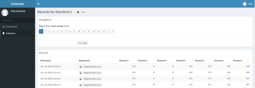
Click the button and you will see information about the recent data received from your Datacase. From here you can also rename the Datacase, download CSV data etc. If you View the raw data, you should see a screen like this:-

The date and time stamp for each one-minute record is shown alongside seven channels of raw data. By default all Datacase loggers will measure the onboard voltage, and the current where there is a load connected too.
The channels you see are:-
- Channel 1 – Onboard voltage, 10-bit, range 0 to 46.2V with 45mV resolution (46.2V / 1024).
- Channel 2 – Onboard current, 10-bit, range 0 to 5A with 4.9mA resolution (5A / 1024)
- Channel 3 – Pulse count, range 0 to 18,000 counts per minute
- – Sensor voltage, range 0 to 4.2V with 4.1mV resolution
- Channel 5 – Sensor voltage, range 0 to 4.2V with 4.1mV resolution
- Channel 6 – Sensor voltage, range 0 to 4.2V with 4.1mV resolution
- Channel 7 – Sensor voltage, range 0 to 4.2V with 4.1mV resolution
The data is delivered in raw form, so to be meaningful it will need to be transformed using a conversion formula.
Examples
- Channel 1 values are the onboard supply voltages across terminals A and B. If the Datacase is powered by a 12V DC power supply, you would see a Channel 1 value of around 265. Multiply 265 by 46.2 and divide it by 1024 to get the actual voltage. i.e. 265 * 46.2 / 1024 = 11.96V.
- Channel 2 values are the onboard supply currents flowing between Terminals B and D. Multiple the raw values by 5 (Amps) and divide them by 1024. If there is no load connected across terminals C and D, Channel 2 will show zeros.
- Analogue channels 4, 5, 6 and 7 measure a 0 to 4.2V range at 4.1mV resolution (4.2V / 1024). These measurements are all referenced to the on board 4.2V regulated supply. Note that there will be some tolerance in this voltage. For highest accuracy results calibrate the measurements.
- Channels 3, 4, 5, 6 and 7 are by default unconnected. When no sensors are connected, current and pulse counts will read as zero. The analogue channels, 4, 5, 6 and 7, if unconnected, will indicate some number roughly around their mid-range (512).
Example for connecting other sensors
Analogue sensors
Aside from the onboard voltage and current sensors, there are a wide range of sensors which can be connected to the Datacase for measuring many different things: temperature, humidity, wind speed, wind direction, pressure and many more. Many of these sensors are designed to produce a small ‘analogue’ voltage range which is proportional to the thing you are trying to measure. In most cases you will give the sensor a fixed power supply (in our case, usually 4.2V) and it will return a lower voltage between 0 and 4.2V.
Measuring higher currents
If you need to measure higher current flows than 5 Amps, you will need to power the Datacase separately to your load, via terminals E and A, to avoid the higher current flows damaging the logger.
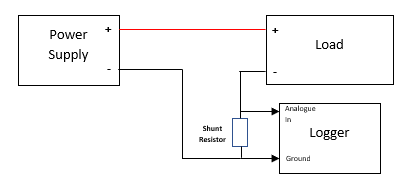
Then, you will need to use a shunt resistor to generate a milli-voltage signal. When electrical current flows through the shunt resistor, a small voltage is produced across the resistor, proportional to the current. This voltage can be measured using one of the Datacase analogue inputs 4, 5, 6 or 7.
The value of the resistor must be calculated carefully to ensure that when the load is drawing its maximum current (including any momentary peaks), the voltage across the resistor does not exceed 4.2V. This can be calculated as follows:
R = 4.2 / Imax
Where Imax is the maximum current drawn by the load. For example, to measure up to 40 Amps, 4.2 / 40 = 0.105 Ohms. So a 100 milli-Ohm shunt resistor would do the trick:https://uk.rs-online.com/web/p/panel-mount-fixed-resistors/1742558/
You also need to calculate the power (heat) that the resistor can safely dissipate. Do this by squaring your current and multiplying by the resistance value. 40 * 40 * 0.105 = 168 W. The resistor above rated at capable of 200W so we are OK. You can see a list of power ratings here: https://uk.rs-online.com/web/c/passive-components/fixed-resistors/panel-mount-fixed-resistors/
Finally, ensure that the shunt resistor is placed on the negative side of the load, as shown below, otherwise the logger may be damaged.

